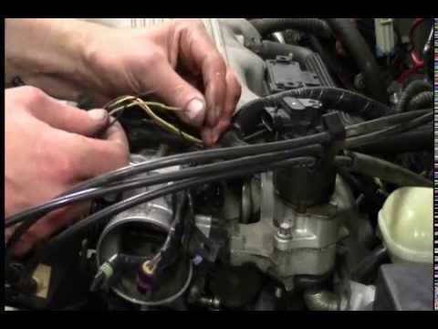
DIY home mechanic diagnosing an intake air temp (IAT) sensor code on a 1999 Malibu. Includes various methods of testing with and without a scan tool and expl…
DIY home mechanic diagnosing an intake air temp (IAT) sensor code on a 1999 Malibu. Includes various methods of testing with and without a scan tool and expl…
You must be logged in to post a comment.
 Diagnosis P1111, P1112, P0113'))
Hi Matt, I have a good one for you. Your help is greatly appreciated. I
have a 2002 Durango 4.7 that has a P0113 code. It doesn’t want to start
when cold. If I do a WOT start, it starts up no problem. It seems like when
the temperature outside is below 70 degrees it has problems. Once either
the car is warmed up or the outside temp is above 70, it starts with no
issues at all. I’ve bench tested the IAT sensor (working perfect). I also
checked the connector (5V). I have no idea what else it could be. I’ve also
done a fuel pressure test and check the injectors (fuel pressure at 48 psi
and no injectors are leaking). Again, any advice would be great.
Hi Matt- Very informative video- I give 4 thumbs up all the way.. My name
is Justin and i have a Question for you regarding the IAT- that maybe you
could help me out with.. I have a 2001 Toyota Tundra v8 that has a crank-
but no start condition. I have recently come upon the IAT sensor as a
possible suspect- that shares the same housing with the MAF apparently.
Anyway i was checking the voltage at the IAT sensor with the ignition
switch in the run position- & found that it has 2.089 volts- about 73
degrees outside tempt.. But when i pulled from the IAT sensor it jumped up
5.03 volts.. My question is simply this. Could that mean my IAT might
possibly be faulty? Any thoughts on that Matt- Thanks Justin.T
Wow, wow, wow!. I was just looking on Amazon today and found this short
detecting device. I though it would be cool to have. But You’ve just sealed
the deal. Thanks, also good explaining the IAT.
ECT 2000 probe. Cool. Briansmobile had shown a similar device, but seeing
it when it fixed something sure was lucky for us all.
Thanks for the joke after 7:20. 🙂 And after 8:20, lol.
Hi Matt, first off I want to say I love your scientific approach to problem
solving and diagnostics. You and ScannerDanner are my anti-parts-changer
YouTube auto-diagnostic idols!
Coming from an engineering/physics background, I am curious about the
nitty-gritty details of how a system works. After understanding the basic
workings, the diagnosis/repair usually come naturally. Like yourself, I am
self-taught when it comes to auto repair, and always gather evidence before
jumping to conclusions and changing parts 🙂
A quick clarification on the IAT functionality and circuit design as I see
it:
In any fuel injection system, at the end of the day the PCM needs to know
the mass flow (not density or volume) of the air entering the engine to
deliver the correct mass of fuel.
In a MAF-equipped engine (like this Malibu), the IAT is actually not
crucial to the PCM’s calculation of air mass entering the engine. In fact,
the MAF or Mass Air Flow hot-wire sensor by design takes into account the
density of the air! A given volume flow of warm air will give a lower MAF
reading than that same volume flow of cooler air, as the cooler air is more
dense and effectively has more mass.
On the other hand, in a MAP (Manifold Absolute Pressure)“speed-density”
configuration, the IAT is a crucial input to the PCM for calculating the
mass air flow. First, the volume flow (liters/sec) of the incoming air
would be proportional to the [engine displacement x RPM]. Now, to get the
mass (g), we need to multiply the volume (liters) of air by its density
(g/liter) inside the intake manifold. From the ideal gas law, we derive
that density (g/liter) is proportional to [pressure / temperature], or [MAP
/ IAT]. So finally we get [mass air flow (g/sec)] ~ [displacement (liters)
x RPM (1/sec) x MAP / IAT]. NOTE: the word “proportional” means that there
is a constant multiplier, so the actual units and numbers work out.
As for the circuit design itself, for a 2-wire thermistor, the 5V reference
wire is the signal wire, which is designed to be pulled to ground
(ScannerDanner explains this concept very well). In other words, there
should never be any voltage on the second wire, as it is a constant ground
(in PCM or external) as you drew in the schematic. So hotter temp → lower
IAT resistance → lower voltage on the ref/signal wire.
I hope that my explanation was helpful and clear, as I had a hard time
wrapping my head around that logic at first! The science and engineering
that is involved in even one sensing circuit, let alone an entire system,
is not trivial by any means! Looks like the modern “shade tree mechanics”
are going to be investing in scanners and scopes soon haha
And that was a really cool tool you used to find the open circuit! Will
have to get one to help pinpointing opens/shorts.
Again, thanks for the great videos, looking forward to more diagnostics!
Ivan
Great video, it really helped me out as always. Just saying, although you
may have a reason for this to avoid confusion, D=Mass/v….it does’t matter
regardless one bit to any other regular person if its explained as weight,
just wanna tell ya but you probably already know this
Good video. Thanks for sharing.
Thanks for the info.
Fyi, you made an error explaining the reference of temperature to voltage
of a IAT sensor. Its the opposite, the colder the air the higher the
resistance and reference voltage & the hotter the air the lower the
resistance and reference voltage. Great video & diagnosis
I think he talks too much and because of that he does’t show more repair
details.
Ooh, that was a good one! Don’tcha just love it when methodical diagnosis
gets real-world validation? 😀
I wanted to make quick mention of a technique for those that find
themselves without a wire tracer/signal sniffer. You can use your
voltmeter to help narrow down the open! Key On, Engine Off (KOEO), take
the positive lead of your voltmeter and probe the positive/reference side
of the circuit, then take your negative lead and touch it to a known-good
ground. If you see your reference signal (usually 5V) on the meter, your
open is on the ground side. If you see 0V, you have an open (or another
problem) on the signal wire. You can confirm this with a simple continuity
test on the ground side. Keep the meter’s ground wire grounded, and probe
the ground/signal side of the circuit. Most sensors run on 5V, at a VERY
low amperage, so continuity is often all that’s required.
There’s a guy here on YouTube under the name ScannerDanner. He’s an
instructor at Rosedale Technical Institute, and his whole deal is
electrical testing and diagnosis using an educated, methodical approach
based on knowledge of circuit design. A lot of the time, he’s using really
crazy high-end automotive scopes and scantools, but the information he’s
giving while doing so can, a lot of the time, apply to much simpler
techniques with much simpler equipment. :-)
Good vid man! That reference to ETCG’s wire soldering video was
hilarious..man his vid was so bad I thought it was a joke lol. GM issued a
Technical Service Bulletin on this issue for this year make and model
relating to these codes. I think in the past somebody had perfumed the
repair for the TSB and did a poor job. Here is the TSB for your reference:
Service Engine Soon Light With Stored Codes P0112, P0113, P1111 or P1112
(Replace IAT Sensor Connector)
1997-2002 Chevrolet Malibu
1997-1999 Oldsmobile Cutlass
1999-2002 Oldsmobile Alero
1999-2002 Pontiac Grand Am
with 3.1L or 3.4L Engine (VINs M, J, E — RPOs L82, LG8 , LA1)
Condition
Some customers may comment that the service engine soon light is on.
The TECH 2 will show stored diagnostic trouble codes P0112, P0113, P1111,
or P1112.
Cause
This condition may be caused by a broken wire at the intake air temperature
(IAT ) sensor connector. The break may not be readily apparent as the
insulation may be intact.
Correction
If routine diagnosis leads to a broken wire at the IAT sensor connector,
replace the connector as follows:
Remove the tape from the engine harness convoluted tube where the IAT
circuit wires join the main engine harness.
Locate/isolate the 2 IAT wires within the engine harness.
Disconnect the IAT connector from the IAT sensor.
Remove the tape from the IAT and MAF (mass air flow) sensor wires to allow
removal of the IAT wires.
Important
Before cutting the IAT circuit wires, it will be necessary to determine the
proper length. You need to add 38 mm – 50 mm (1.5 in – 2.0 in) to the
length of the wire going to the IAT. Also, when cutting the IAT circuit
wires, it is important that the wires are cut in a manner that will not
create a large mass. Stagger the cuts and install the connector kit.
Original connector cavity “A” has a red wire and cavity “B” has a tan wire.
Make sure cavity “A” and cavity “B” wires on the replacement pig tail
connector match “A” and “B” wires on the engine harness. This will provide
strain relief and prevent recurrence of this concern.
After staggered cuts are made on the IAT wires in the engine harness, strip
a small amount of the insulation from both wires and install the kit butt
connectors to the bare IAT wires by crimping both.
Stagger the cuts on the pig tail wires to match the IAT engine harness
wires.
Strip a small amount of the insulation from the pig tail IAT wire ends.
Install and crimp both wires into the open end of the butt connectors that
were installed on the engine harness IAT wires.
Heat shrink both IAT butt connectors and let the wires cool off.
After cool down is completed, the harness can be neatly taped with
electrical tape.
Install the IAT connector on the IAT sensor.
Clear the codes.
Parts Information
Part Number
Description
Qty
12102620
Connector Pig Tail
1
nice video very well explain thank you for taking the time
Hallo . my fiat stilo showing me sensor temp failure . i have change the
sensor temp . intake air temp . thermostat . and everything getting
voltage. checking from ecu to the sensor is good. there is not cutting .
but i still get this error and the car not starting when this error comes
on
excellent video…Thanks !!!
The circuit for the IAT sense is slightly different than you drew on the
white board. Inside the ECM you will likely find a series resistor to
ground on the signal lead. This forms a voltage divider circuit that is
read by an analog to digital converter in the ECM.
I have the Power-probe Master kit as well and yes, it has definitely paid
for itself. I’ve ran into this exact issue and you did exactly what needed
to be done, good job Matt. Remember, when the engine is stone cold, all
temp sensor signals should be identical if not close. You can quickly do a
rationality check with a scan tool by looking at all the temp sensors.
i feel the same way when i fix something like this. i had the same problem
with a honda mb-5 motorcycle cdi unit that had an open from the pickup
coil. great video
So u traced the signal wire rather then the 5 volt ref wire??
A great video Matt .
Thanks for the info on the signal meter info, Matt! The amount of times I
have had to completely unwrap a harness to find that exact issue makes me
very happy to find the tool that saves time! Agreed: far too many
unnecessary parts are being sold because of lack of knowledgeable diagnosis
(I wish I owned shares at AutoZone)
Excellent video thanks.
Well done Matt.
hey, great video..keep up the good work
I can’t wait for next one
What camera are you shooting with? The aspect ratio is odd. It’s almost
16:9 widescreen, but not quite. You should look into that.
I like the way you go about trouble shooting things. Great videos, thank
you for sharing Matt.
Now that I think about it, a day too late, A review on the Power-Probe
would be awesome, especially with your sense of humor. I know for a fact
the tool is…well, simply put, Badass.
Scannerdanner brang me to this channel and now im here to stay. Love your
thought process going into a diagnosis