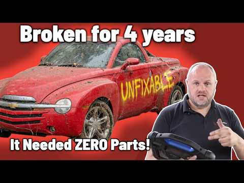
This Chevy SSR has been broken for 4 years and has already had multiple parts replaced in an attempt to fix it but the problem is still there.
The customer complaint is easy to confirm because as soon as we start the engine it runs terrible.
We hook up the scantool and immediately find multiple fault codes stored but instead of throwing more parts at the vehicle we start diagnosing the problem step by step.
As the diagnosis unfolds we discover that this Chevy SSR doesn’t have just one problem… it has two completely separate issues causing the symptoms.
After testing, troubleshooting and following the evidence we’re able to get this SSR running properly again…
Without replacing a SINGLE part!
This is a great example of why proper diagnostics can save a lot of time, money and unnecessary parts replacement.
Watch the full diagnosis to see what was actually wrong and how we found it!
If you enjoy real-world automotive diagnostics, electrical troubleshooting, scantools, and fixing vehicles without guessing make sure to like, subscribe and leave a comment!
#ChevySSR #automotivediagnostics #mechanic #mechaniclife #diagnostics #checkenginelight #scantool #autorepair #chevrolet #troubleshooting
Check out my Second channel;
/ @ddtsb
Check out my website ; https://www.diagnosedan.com
For Diagnosedan Tsb visit : https://www.diagnosedan.com/diagnosed…
For the Topdon tool used in the video:
US: https://www.topdon.us
UK: https://www.diagnosticconnections.co.uk/
EU: https://eu.topdon.com
For business inquiries ( not for technical questions!); Diagnosedan@gmail.com or fill out the contact form at Diagnosedan.com
)
Check out my Second channel;
/ @ddtsb
Check out my website ; https://www.diagnosedan.com
For Diagnosedan Tsb visit : https://www.diagnosedan.com/diagnosed…
For the Topdon tool used in the video:
US: https://www.topdon.us
UK: https://www.diagnosticconnections.co.uk/
EU: https://eu.topdon.com
Amazing diag time
great sounding engine after the fix
Great diagnosis. All that frustration over a loose pin. The owner must be incredibly angry and relieved at the same time. Good job, but FFS, drop that intro song. It is horrid.
This car is uglier than the Fiat Multipla
please don't do that AI intro again…. that was shocking!
Sorry but that intro was ….. not good…
Danny, tip, je kunt een ordinaire webcam aansluiten op een webcam aan een lange USB kabel. Dan kun je live meekijken met het gedrag van de gasklep. Scheelt wat tijd.
maybe a strange question, but was wondering how it ran with 4 year old gas (you said you were going to take it on a test drive to warm it up). ?
Hey buddy you don't know me and I don't know you (first time clicking on one of your videos). Feel free to ignore my advice, I'm not a video expert, just noticed what other youtubers normally do. First thing that struck me was the AI song (real talk: they are repulsive and everyone hates them), and then the fact that you show yourself in the intro instead of showing cars and how you fixed them. You'd show yourself in the intro if you're famous or very charming like Derek from VGG, otherwise what's the point, people just want to see cars and repairs. Also, you might want to begin with a cold open with short clips from the rest of the video before the intro, to catch the viewers' interests, if you really want to have an intro.
According to TOPDON the T120A Battery Charger in Supply Mode can provide a power of 1700 Watts to the output. At 120 Amps the output should be able to achieve 14 Volts at the output, but not at the clamps due to the voltage drop in the cables at 120 Amps, and certainly not through clamps that do not have a high current strap, like the TOPDON factory clamps shown in the video.
The common trend with whole vehicle power supplies, rated at 50 Amps or more continuous at 16 VDC at the clamps, is to use braid strapped cable clamps. A braid strapped cable clamp is a large cable clamp that has a tin plated copper braid with lug ends connected between the two jaws inside the clamp so current from the cable input side can also flow through the other jaw. Relying on a pure copper sliding pivot surface to conduct between the to jaws, like the T120A cable clamps shown in the video, is not effective at high currents, and gets worse as the exposed copper starts to oxidize (age). For a cable clamp to work well at high currents we need to have both jaws sharing the current, given the fact that a pointy jaw tooth by its shape does not have a lot of contact surface to conduct current.
(Side note: The proper way to describe the T120 operation in power supply mode, is to call it a "vehicle power maintainer" and not just say maintainer, and certainly not a battery maintainer. Historically, a battery maintainer (or just maintainer) refers to a trickle charger used to top off the battery (maintain the battery) when garaged. A more descriptive term is to call the power supply mode a "whole vehicle power supply and charger" (which is TOPDON's approach to put supply as just another charging mode, and not a standalone DC power supply, which would require providing an operational specification like noise for example, which TOPDON does not provide.)
Given the above many technicians make up their own cables and cable clamps for the T120A, based on the Anderson SB120 present on the T120A output on the back. The common approach is to make a 1 AWG SB120 extension (usually less than 12 feet), and then a 3 foot SB120 clamp pigtail to connect to the vehicle using the proper strapped clamps.
I think, given the multi-year hack job on the vehicle diagnostics and repair, you should address all of the power distribution and control DTCs before anything else, especially if a third party claimed to repair the power distribution box. So, I think you should have started with P0689-00 and P1682-00 rather than the TB codes for a TB that has been replaced twice.
I am curious why you don't use your DMM on DC Volts and a parallel resistive dummy load (e.g. 15 Ohms) to test your power and grounds at the ECM? Perhaps you do not trust your DMM? If your channel claims to teach, you should teach your viewers to trust their DMM and not use a incandescent test light dummy load, which tells you nothing about the circuit except it makes some light. Who taught you to use an incandescent test light over a DMM and resistive dummy load?
Once you connect a high current variable regulated whole vehicle power supply to maintain vehicle power and charge the battery you have the ability to set the voltage to a desired level anywhere you want, like the DLC or the power distribution box or the ECM. Once you set this "reference" voltage all of your DMM voltage reading with a known resistance dummy load tells you so much more about the circuit than an incandescent test light.
In the USA working at an OEM or Tier one Supplier (the company that designed and built the ECM you are testing in the video) as an electrical engineer, electronic technician, or mechanic you will never see a incandescent test light used as a dummy load. All testing is DMM centric (e.g. Fluke 87V). If you need a load just introduce it in parallel to the DMM on DC Volts. If you need a light for a wiggle test put a LED based wiggle light (250mA load current) across the load resistor, if you want sound based wiggle test, but a low current piezo buzzer across the load resistor. Both the LED and the Piezo buzzer are much better at a wiggle test because they are at least 10 times as fast as compared to an incandescent light bulb that needs time to heat up.
The ECM tin braided strap is not a power ground, it is a chassis ground, chassis meaning ECM enclosure and not vehicle chassis. Calling an electronic instrument case a chassis is a very old tradition. Most EE ECM packaging engineers will use the term case and chassis interchangeably. The ECM case ground is usually capacitively coupled (impedance coupled) to the power ground. From a DC test light stand point the reason the test light lit up was because the current is returning to the vehicle chassis through the strap and not through the ECM. The tin braided strap is better described as a EMC ground.
You can use a test load to see if the ECM low side relay coil circuit wiring is working to control a relay, but you always do it with the ECM connector disconnected and the load applied directly to the front of the connector pin with a pin jumper of the correct type.
To test the relay circuits, it is best to connect a relay signal break out before going key on. You can then verify the relay is working with a DMM. When you go ignition on and remove and reconnect the relay, this will store a code in the ECM. A stored code can be easily cleared by a scan tool, but the code may change how the module operates. A DTC is just not a flag, it can indicate a change in operation, that is, a change in how the strategy operates. A newer relay test tool from AESwave called uActivate Master Kit can speed up this testing.
The TP motor is controlled by a full bridge PWM algorithm which will control current through the a DC brush motor (MY 2007) as part of a servo position control system. What is being controlled is current through the motor. You can diagnose the system much quicker if you use a current clamp with the Pico scope to monitor one of the motor wires.
It is a bit strange that you start the car with the TOPDON clamps connected. The TOPDON is protected against reverse current flow, which is good, but with the engine running a clamp could fall off potentially shorting something out or falling into a belt or fan.
Brilliant job Dan.
That's a very thorough diagnosis. And once again, it was spot on. How long did the diagnosis take?
Hey dan please can you tell us what program you are using for diagrams?
Nice work…
Chasing broken wires and loose connections can be a challenge.
Fantastic video, Dan you have to work hard but I love watching this video. I love your thought process and the way you go about things outstanding diagnosis Work as always.
Those hood claws are brutal. A friend has an SSR and any time we're doing work, he'll throw a sliced pool noodle on the whole edge of the hood.
That car needs a new wiring loom for shure. As a maintenance tech I ask my self: " why nobody checked the wiring?" (Add some Italian swear words in-between).
Man, that AI music is really bad. I realy liked the old intro.
D dan does the best videos. I'm thinking that if you think you have a problem with the wire you should just start pulling on it from one end to the other. Once you thought it could have been the pink wire you should should have tugged on it. And checked the continuity from one side of the wire to the other side.